In this tutorial, I’ll run through 3 ways to solar power an Arduino (or Raspberry Pi).
These methods all:
- Use a 3.7V or 12V battery
- Power the board via the USB port
- Require no soldering
Let’s get started.
1. DFRobot Solar Power Manager 5V

This little board is the DFRobot Solar Power Manager 5V, and it’s currently my favorite way for solar powering an Arduino. It’s cheap and works with common 3.7V lithium batteries — such as 18650 and LiPo batteries. And there’s no soldering or tiny components required.
Parts

- DFRobot Solar Power Manager 5V
- 5V solar panel
- 3.7V lithium battery with a compatible battery holder (or 3.7V LiPo battery with JST connector)
- Arduino with USB cable
Tools

Step 1: Connect the Battery to the Solar Power Manager
Locate the battery terminals on the Solar Power Manager. There are two sets. The white battery terminals on the left are for a battery with a JST connector. The green ones on the right are screw terminals for battery leads. In this example, I’m using an 18650 battery in a battery holder, so I’ll use the green ones on the right.

Connect the battery holder leads to the green battery terminals. Or, if you’re using a battery with a JST connector, plug it into the white battery terminals.
Note: When using a battery holder, I like to connect the battery leads before inserting the battery to limit the chance of accidentally shorting the battery.

Put the battery in the battery holder. The board won’t turn on just yet.

Locate the BOOT button on the board. It’s next to the JST port.

Press the BOOT button to turn the board on. Once you do, you should see the ON light turn on.

Step 2: Connect the Solar Panel to the Solar Power Manager
Locate the solar terminals on the Solar Power Manager. They’re the other set of green screw terminals.

Connect the solar panel leads to the solar terminals.

Place the solar panel outside in direct sunlight.

Confirm that the red CHG light turns on.

Your solar panel is now charging your 3.7V battery. All that’s left to do is connect the Arduino.
Step 3: Plug the Arduino into the USB Port
Plug your Arduino into the USB port on the Solar Power Manager. It should turn on and start running your code! To illustrate that my Arduino was working, I uploaded a simple program to turn on an LED. As you can see, the LED is on. 🙂

Done!
The Solar Power Manager will continue solar charging the battery until it’s fully charged.
Note: You can also use this board to charge your lithium battery via micro USB. Just plug it into the USB IN port.
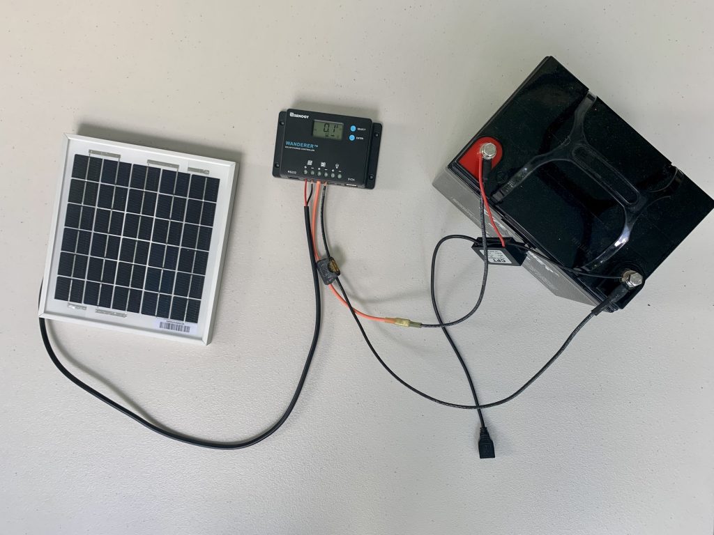
2. Solar Charge Controller with USB Port

A solar charge controller sits between the solar panel and battery. It regulates the solar panel’s voltage and current to safely charge the battery and prevent overcharging.
Charge controllers are incredibly common in 12V (and higher) solar power systems. And some, like the budget-friendly Renogy Wanderer 10A, have a USB port that you can use to power your Arduino or Raspberry Pi.
The downside to this approach is that it’s costlier and a bit more involved than the first method.
Parts

- Small 12V solar panel
- 12V PWM charge controller with USB port
- Small 12V battery
- Battery to charge controller adapter cables with fuse
- Arduino with USB cable
Tools
- Screwdriver
Step 1: Connect the Charge Controller to the Battery
Locate the battery terminals on your charge controller. They will usually have a battery icon or the letters “BAT” or “BATT” next to them.
Note: If you’ve never worked with a charge controller before, it’s helpful to know that you almost always connect the battery to the charge controller first before connecting the solar panel. And you almost always disconnect the solar panel first before disconnecting the battery.

Connect the charge controller to battery adapter cables to the battery terminals on the charge controller. The positive cable should have a fuse. Look in your charge controller’s manual for the recommended fuse size.
Note: As before, I like to connect the battery cables to the charge controller FIRST to limit the chance of accidentally shorting the battery.

Connect the battery cables to the battery terminals. Your charge controller should turn on when you do. (In this example, I’m using a larger 12V 33Ah battery that I already had. Your 12V battery will probably be smaller and have different terminals than mine.)

Select your battery type. Follow the instructions in your charge controller’s manual on how to select your battery type (e.g. sealed, gel, flooded, lithium). In this example, I’m using a sealed lead acid battery, so I set my battery type as sealed.
Note: This is an important step! Charge controllers use different charging profiles with different voltage set points based on battery chemistry. If you don’t select the right battery type, it can shorten the lifespan of your battery.

Select the right load settings. In some charge controllers, you can choose when and for how long the USB port is on. I set mine to setting 17, which, for my controller, means the USB port will always be on.
Note: If your charge controller has load terminals, the load settings will also control those.

Step 2: Connect the Solar Panel to the Charge Controller
Locate the solar terminals on the solar charge controller. They will usually have a solar panel icon or the letters “PV” next to them. (PV refers to PV modules, which is another way of saying solar panels.)

Connect the solar panel’s cables to the solar terminals. If your panel is big enough — such as 50W or greater — then its cables probably have MC4 connectors. If that’s the case, you’ll need to use solar panel to charge controller adapter cables to connect your panel.

Place the solar panel outside in direct sunlight.

Confirm that the battery starts charging. Once your panel is receiving enough sun, the charge controller should indicate somehow that the battery is now being charged. It may do this by flashing an LED or showing a charging icon on its display. Many charge controllers with displays also have a PV current screen that shows the charging current. For example, mine shows a PV current of 0.2A, so I know the battery is charging.

Step 3: Plug the Arduino into the USB Port
Plug the Arduino into the USB port on your charge controller. It should turn on and start running your code! As before, I programmed mine to just turn on an LED to illustrate that it’s on and working.

Done!
Here’s what my completed setup looked like:

3. Solar Charge Controller with 12V to 5V Converter

If your charge controller doesn’t have a USB port, you can still solar power your Arduino using its load terminals and a 12V to 5V buck converter.
Note: If your charge controller has neither load terminals nor a USB port, jump to the alternative steps below for how to connect the 12V to 5V converter directly to the battery.
Parts

- Small 12V solar panel
- 12V PWM charge controller with load terminals
- Small 12V battery
- 12V to 5V converter with USB port
- Battery to charge controller adapter cables with fuse
- Arduino with USB cable
Tools
- Screwdriver
Step 1: Connect the Charge Controller to the Battery
Locate the battery terminals on your charge controller.
Connect the charge controller to battery adapter cables to the battery terminals on the charge controller. The positive cable should have the correctly sized fuse.
Connect the battery cables to the battery. Once you do, your charge controller should turn on.
Select your battery type. Follow the instructions in your charge controller’s manual on how to set your battery type (e.g. sealed, gel, flooded, lithium). I selected sealed because I’m using a sealed lead acid battery.
Select the right load settings. In some charge controllers, you can choose how long the load terminals stay on. Follow the instructions in your controller’s manual. I set mine to mode 17, which means they’ll be on for 24 hours a day.
Step 2: Connect the Solar Panel to the Charge Controller
Locate the solar terminals on your charge controller.
Connect the solar panel’s cables to the solar terminals.

Place the solar panel outside in direct sunlight and confirm that the battery begins charging. Your charge controller should indicate in some way that the panel is charging the battery.

Step 3: Connect the 12V to 5V Converter to the Charge Controller
Locate the load terminals on your charge controller. They will usually have a lightbulb icon or the word “LOAD” next to them.

Connect the converter to the load terminals.

Step 4: Plug the Arduino into the USB Port
Plug your Arduino into the converter’s USB port. It should turn on and start running your code! Once again, I programmed mine to turn on an LED to show that it’s on and working.

Done!
Here’s what my completed setup looked like:

Alternative Method: Connect the 12V to 5V Converter Directly to the Battery
If your charge controller doesn’t have load terminals, don’t fret! You can connect the 12V to 5V buck converter directly to the battery. You’ll need a couple more things, though.
Extra Parts & Tools

- Wire connectors that fit your 12V battery
- Wire crimper
- Heat gun (if using heat shrink wire connectors)
Step 1: Crimp the Wire Connectors to the 12V to 5V Converter
Grab the appropriate wire connectors for connecting the converter to your 12V battery. For instance, I used some ring terminals that were big enough for my battery terminals.
Tip: Pick up a good wire connector variety pack. It’ll save you the hassle of having to buy different wire connectors for every project.

Crimp the wire connectors to the wires of the 12V to 5V converter. If needed, shrink the heat shrink with a heat gun.

Step 2: Connect the Charge Controller AND Converter to the Battery
Connect the charge controller to battery adapter cables to the battery terminals on the charge controller. The positive cable should have a fuse. Don’t connect them to the battery just yet.
Connect the charge controller AND 12V to 5V converter to the battery. Your charge controller should turn on.
Note: If the terminals on your 12V battery are can’t fit multiple connectors, you can always wire the charge controller and 12V to 5V adapter to busbars or a fuse block.

Select your battery type. I’m using a sealed lead acid battery, so I selected that option.
Step 3: Connect the Solar Panel to the Charge Controller
Connect the solar panel to the solar (PV) terminals on the charge controller.
Place the solar panel outside in direct sunlight. Once you do, your charge controller should indicate that the solar panel is now charging the battery.
Step 4: Plug the Arduino into the USB Port
Plug your Arduino into the USB port on the 12V to 5V converter. It should turn on and start running your code! Once again, I programmed mine to turn on an LED to show that it’s on and working.

Done!
5 Tips for Solar Powering an Arduino
1. Pick the Right Board for Your Project
In all these examples, I used the Arduino Uno because it’s the most popular Arduino board. However, it’s not the most energy efficient. You can save yourself money on the battery and solar panel by picking a board that is more efficient and has only the features you need.
For example, you can consider a board like the Arduino Nano. It has the same microcontroller as the Uno, but consumes less power.
2. Reduce Your Arduino’s Power Consumption
Once you’ve got your board, there are some steps you can take to reduce its power consumption. The goal here is to make your board consume as little power as needed so that you can save money by getting a smaller battery and solar panel.
Here are some quick tips:
- Use the official Arduino low power library to enable low power features
- Use the sleep and deep sleep modes when possible
- Remove unneeded sensors and hardware
Check out this tutorial from Maker Pro and this one from SparkFun for more ideas and in-depth instructions.
3. Perform an Energy Audit to Size Your Battery and Solar Panel
Power consumption reduced! ✅
Now you can estimate your board’s average power consumption, or use a good USB power meter to measure it exactly.

Using my USB meter, I see that my Arduino Uno is consuming 0.2W. That works out to 40mA at 5V. And I’ll leave it running for 24 hours a day.
With that info, I multiply watts times hours to get its average daily power consumption in watt hours.
0.2W * 24 hrs = 4.8Wh
So, in this example, my Arduino consumes 4.8 watt hours per day.
Let’s say I want a battery that can power my Arduino for 3 days straight before being recharged.
4.8Wh * 3 = 14.4Wh
My battery needs to be at least 14.4Wh, but ideally a little bigger to account for losses and reduction in battery capacity over time. So I’ll look for a battery that has a capacity closer to 20Wh.
After doing some research, I decide to get two 3.7V 3000mAh 18650 batteries and wire them in parallel, to make a 3.7V 6000mAh battery bank. That works out to 22.2Wh (calculation: 3.7V × 6000mAh ÷ 1,000 = 22.2Wh).
Let’s say I want a panel that can recharge the battery in a day. There are many different ways to go about sizing a solar panel for a project, but I’ll keep it simple. A rule of thumb I’ve used before is that a solar panel — at many latitudes and locations in the US and Europe — can produce on average around 4Wh/W per day when mounted in a sunny spot.
Based on that, I’ll pick at least a 6W solar panel, which could produce around 24Wh per day based on that rule of thumb. That will mostly recharge my battery from empty after taking into account its 22.2Wh capacity and the Arduino’s 4.8Wh daily power consumption.
Note: If using a PWM solar charge controller in your setup, you’ll want to increase that size a little to account for the power consumption of the charge controller. I’d maybe go with a 10W solar panel in that scenario, for instance.
4. You Can Also Power Many Arduino Boards with 7-12V to the DC Jack or VIN Pin
You could also power your board by connecting a 2.1mm x 5.5mm DC plug to the battery or the charge controller’s load terminals and plugging it into the board’s DC power jack. If you did that, you wouldn’t need to use a 12V to 5V converter.
The downside to this, though, is that 12V batteries often output greater than 12V. A 12V sealed lead acid battery is fully charged at around 12.9 volts, for instance. And a 12V LiFePO4 battery is fully charged at 13.6 volts. (The voltage of the load terminals has matched the battery voltage every time I’ve measured it.)
Some boards, such as the Uno, have an input voltage limit of 20V. But, according to the official Arduino Uno product page, “if using more than 12V, the voltage regulator may overheat and damage the board.”
I’m not sure if an extra 0.5-1V will do long-term damage to your Arduino. I’ll leave it up to you whether or not you want to risk it. 😉
5. Mount the Solar Panel at the Optimal Tilt and Azimuth Angle for Your Location
Use our solar panel angle calculator to calculate the right tilt angle for your location.
For the azimuth angle (direction), a simple rule of thumb is to face your panel south if you live in the northern hemisphere, and north if you live in the southern hemisphere.
And, of course, mount the panel in a spot that receives lots of direct sunlight throughout the day. 🌞